Offshore structures
The fossil fuel and renewable energy industries both rely heavily on offshore platforms and infrastructure constructed on the seabed of the shallow seas around the UK. While the platform designs vary, for example to suit water depth, injected concrete is commonly used to transfer the loads between steel substructures within their foundations. Wind turbines, for example, use a range of foundation designs including the gravity (or monopile) foundation for shallow water depths (less than 30 m) or the tripod foundation for deeper water depths (down to 60 m). The foundations in all cases incorporate load transfer through steel-concrete-steel substructures (Figure 1).
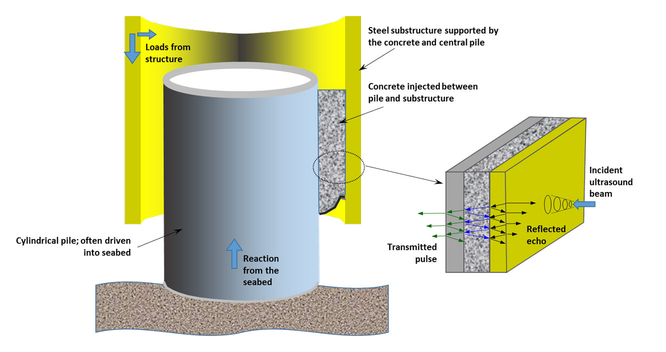

Figure 1 Principal foundation for offshore infrastructure constructed on the seabed. BGS © UKRI.
Inspection of concrete grouts
The foundation substructure can be represented by a three-layer system bound by water inside the cylindrical pile and the open sea surrounding the substructure, shown in the inset in Figure 1.
This three-layer system can be inspected using a low-frequency beam of ultrasound. Incident ultrasound is partially reflected and transmitted from the substructure’s outer surface. The transmitted wave enters the structure to be partially transmitted and reflected at each boundary surface between the steel and concrete layers. Thus, the ultrasound waves backscattered from and transmitted through this layered sequence are the result of a superposition of a series of the original incident wave that has been modulated by partial reflection and transmission, and delayed via multiple transmissions across the thickness of the bound structural layers (Figure 1 inset).
The echo-reflected signals are modulated and exhibit characteristic notches in their magnitude spectra that are signature characteristics not only of the material layers, but also of any small water gaps between individual solid layers.
Wave propagation through foundation models
The concrete is subjected to large, complex stresses leading to progressive deterioration in the foundation condition, manifested in a range of defects such as debonding and the growth of gaps at its interfaces with the steel substructures, or even a complete loss of concrete in parts of the annulus (Brett et al. 2018).
We modelled the wave propagation through this three-layered system to evaluate the potential sensitivity of an echo ultrasound inspection method to these effects. The model outcomes include predicted spectra for a three-layered foundation system in good condition, i.e. with no gaps between the concrete and either of the bounding steel substructures (shown as the red plots in Figure 2), and the spectral characteristics related to front gaps (left-hand plots in Figure 2) and rear gaps (right-hand plots). This modelling yielded notable results.
Results
Increasing the aperture of a front gap from 0.1 mm to 1 mm causes the notch at 53.3 kHz to diminish in depth and shift to lower frequencies. The notch at 60.75 kHz also shifts to slightly lower frequencies but deepens and the notch at 73.8 kHz shifts to lower frequencies (Figure 2, left-hand plot).
Increasing the aperture of a rear gap from 0.1 mm to 1 mm causes the minimum at 53.3 kHz to shift to lower frequencies while maintaining a constant depth. The minimum at 60.75 kHz diminishes while also shifting to slightly lower frequencies and the minimum at 73.8 kHz grows and shifts to lower frequencies (Figure 2, right-hand plot).
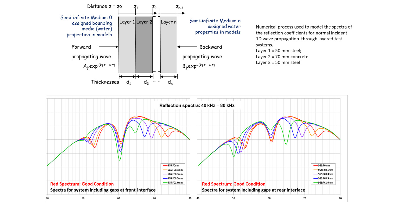
Figure 2 Ultrasound wave propagation through foundation model, showing effects on front and rear gaps. BGS © UKRI.
Diagnosing concrete condition in foundations
Our numerical modelling indicated that it was feasible to inspect the condition of offshore foundations using an echo-ultrasound method. The model outcomes provided the baseline echo spectra used to distinguish defected foundations from those in good condition. Experimental replication of these baseline spectra would then provide very compelling evidence and the impetus for development of an inspection platform for offshore deployment.
Figure 3 shows a large ultrasound transducer (150 mm2) used to transmit ultrasound pulses towards the layered steel-concrete-steel target and to detect the echoes from this target. The black plots in the left- and right-hand graphs in Figure 3 show the spectrum for a target in ‘good condition’, i.e. where the concrete is in contact with both steel plates.
In Figure 3, note how the notch at 54 kHz diminishes and shifts to lower frequencies with the introduction of a front gap of increasing aperture; note also how the notch at 61 kHz deepens and shifts to lower frequencies.
Note how the notch at 54 kHz deepens and shifts to lower frequencies with the introduction of a rear gap of increasing aperture; note also how the notch at 61 kHz diminishes and shifts to lower frequencies. These are the same responses as the modelling outcomes and these very different responses verified the great potential for applying echo ultrasound to inspect offshore foundation condition.
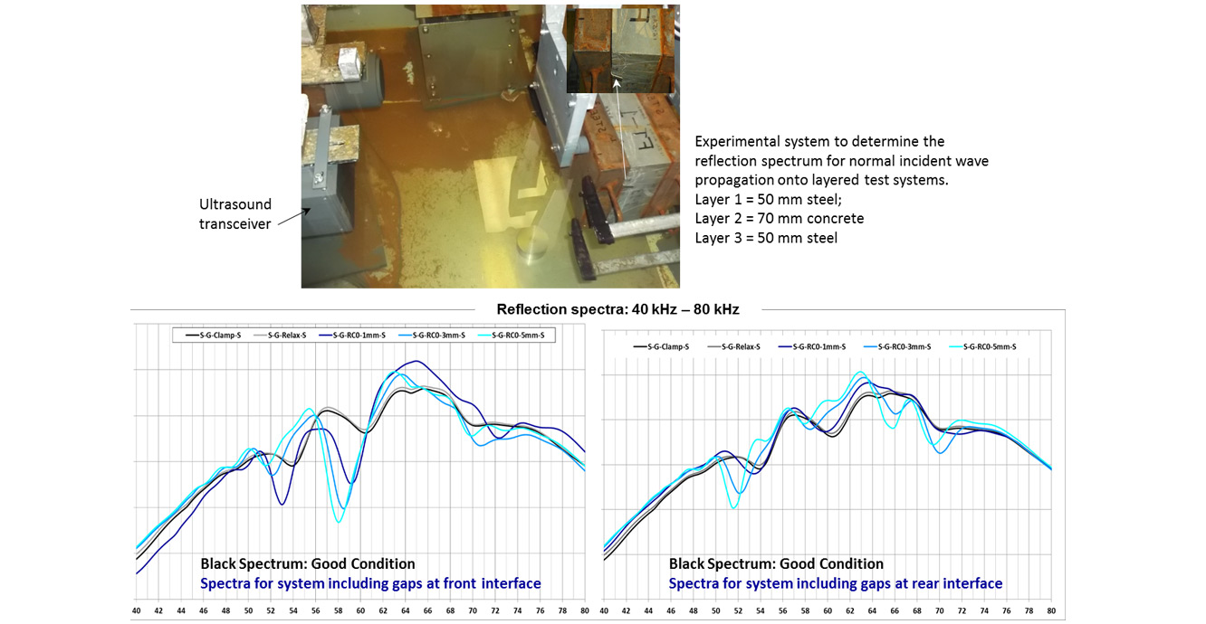
Figure 3 Ultrasound wave propagation experimental samples showing effects on front and rear gaps. BGS © UKRI.
Field ultrasound inspection system
The laboratory bench top modules were condensed onto a ROV-deployed field system shown in Figure 4, which comprised:
- a PC laptop
- a combined arbitrary wave generator (AWG) digital storage oscilloscope (DSO)
- a sonar pulser-receiver
- a sonar probe (or ultrasonic transducer)
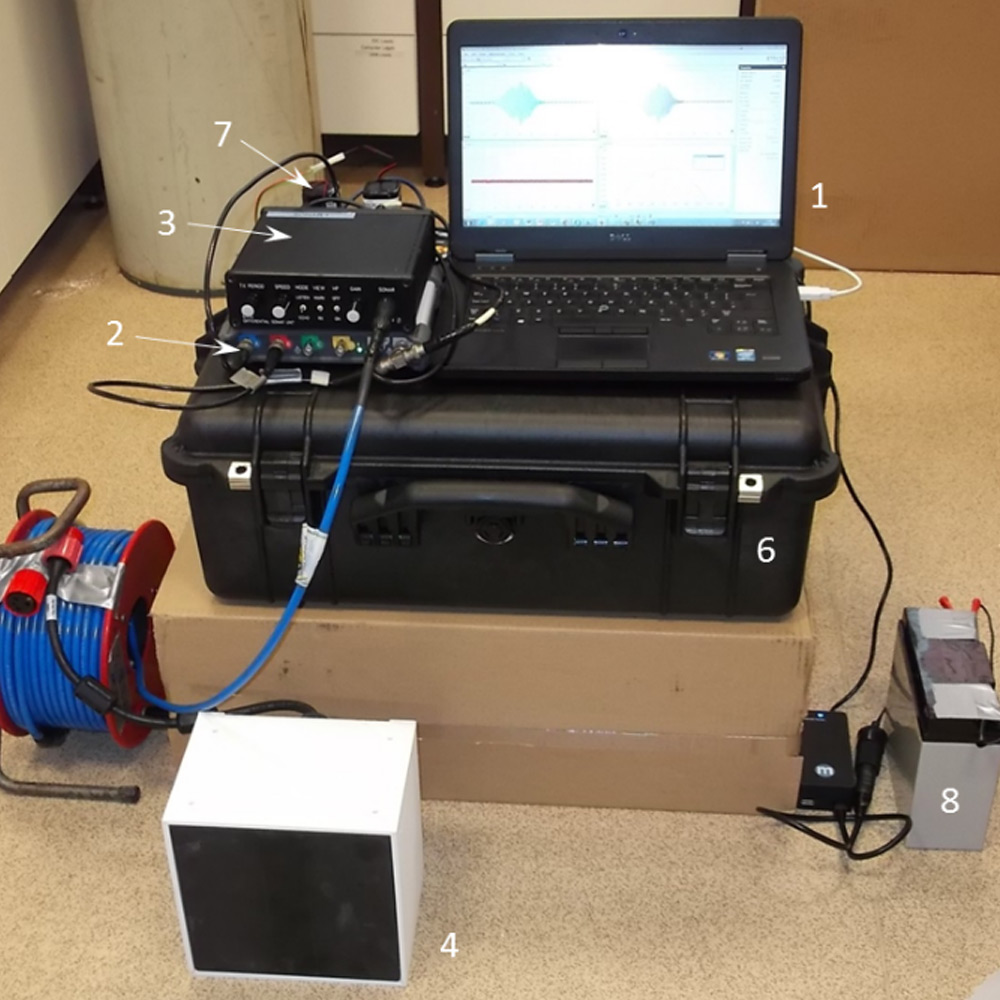
Figure 4 Ultrasound field inspection system. BGS © UKRI.
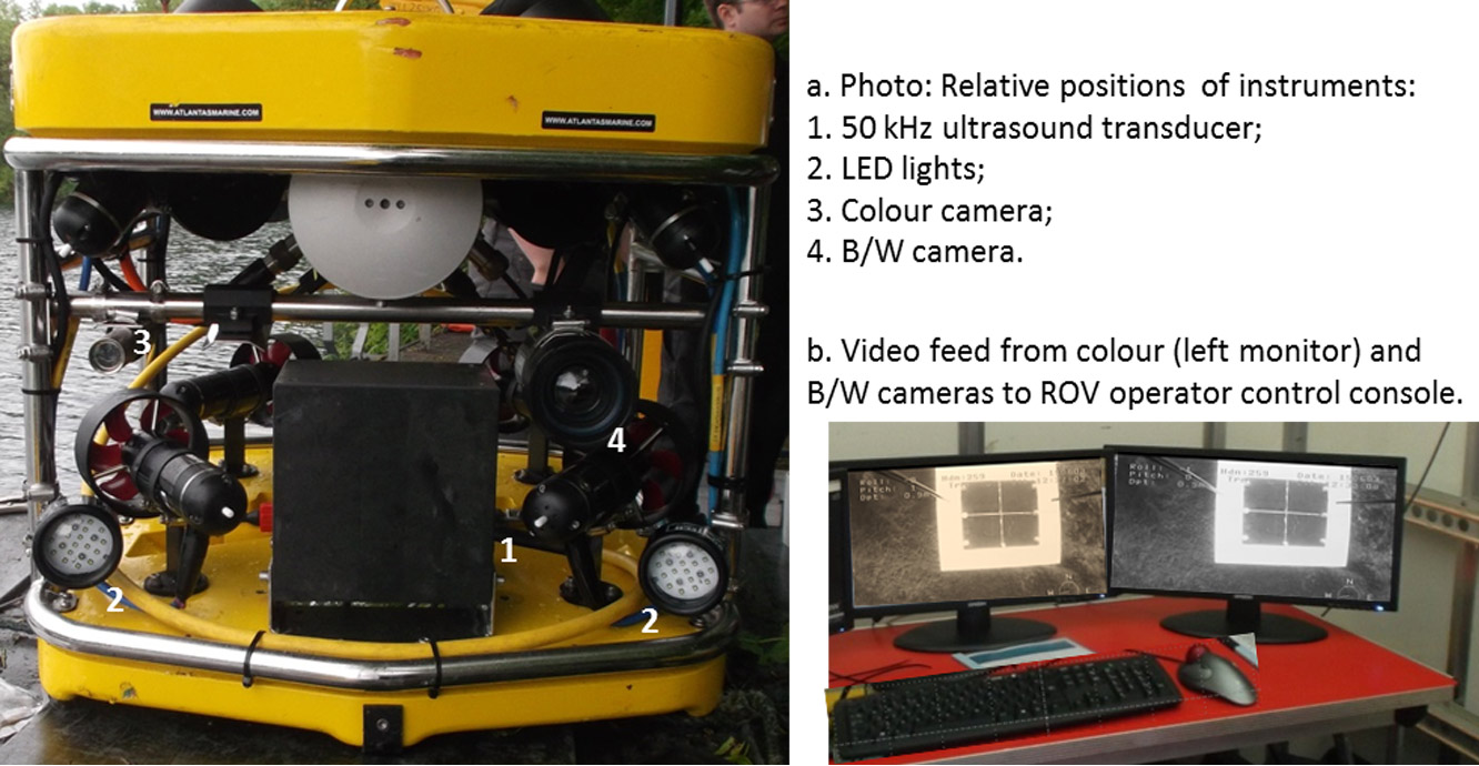
Figure 5 The sonar probe of the field ultrasound inspection system mounted onto an ROV. BGS © UKRI.
This system was deployed from a remotely operated vehicle (ROV), which had complete and independent yaw, pitch and roll (Figure 5). The sonar probe was centrally mounted on the front of the ROV along with lights and cameras to aid visibility. For example, Figure 5b shows a view of an underwater target about to be inspected. Note that the spacer bars are visible on either side of each view. These were used to maintain a constant echo offset for all inspections.
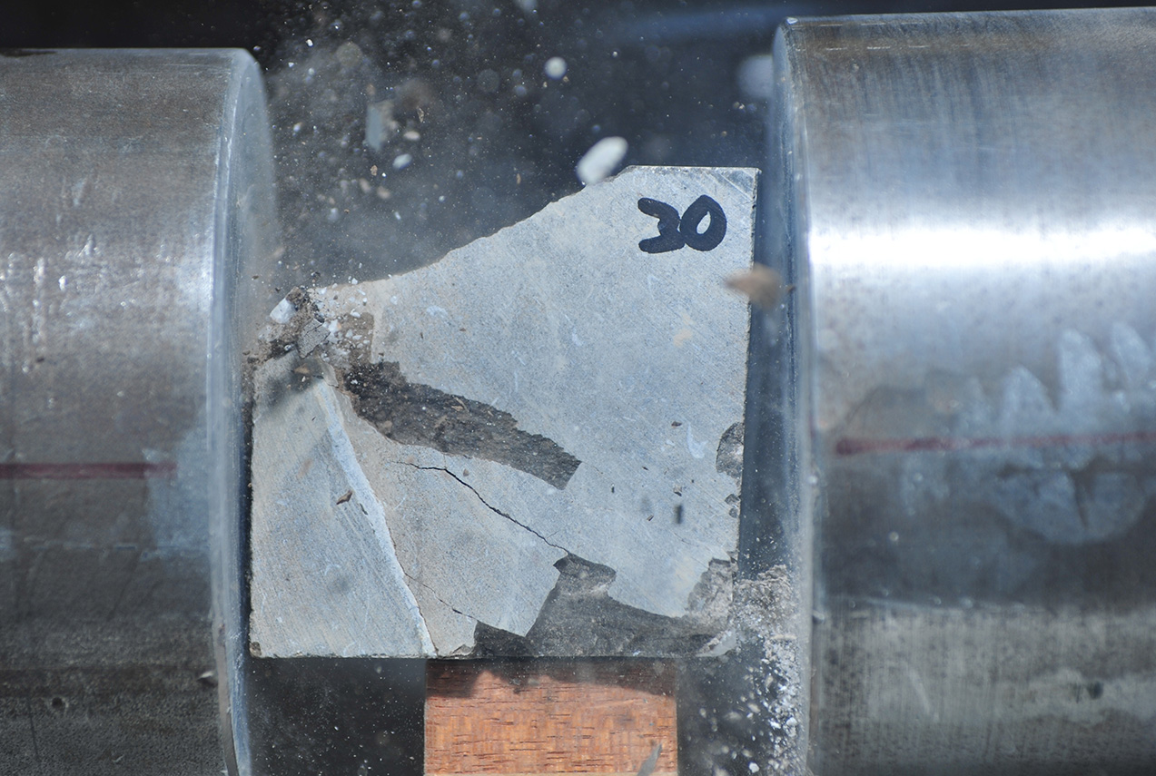
This platform was tested in a diving pool by recording echo reflections from a 0.5 m × 0.5 m square target comprising a 50 mm front steel plate, a 70 mm concrete centre layer and a 50 mm rear steel plate (Figure 6). The field trials consisted of a similar matrix of experiments to the laboratory trials whereby echoes were recorded from targets in ‘good condition’ and with defects including front and rear gaps.

Figure 6 Field trials of ROV-deployed echo-ultrasound inspection system. BGS © UKRI.
Our early field trials were very encouraging because we gathered data that confirmed our findings from the numerical models and also from the laboratory experimentation. For example, Figure 7 compares the spectra for a steel-concrete-steel target in good condition (black plot in both right- and left-hand graphs) with the spectra from targets with gaps between the concrete and the front steel plate (left-hand graphs) or the rear steel plate (right-hand graphs). Note how the higher frequency notch at 59 kHz develops as the front gap increases, whereas the lower frequency notch at 57 kHz develops as the rear gap in aperture.
Our aim is to follow up these field trial with further trials on actual offshore infrastructure.
Relative topics
You may also be interested in:

Science facilities
BGS operates and maintains a wide range of state-of-the-art laboratories and other facilities, which underpin virtually all of our research.
Engineering and Geotechnical Capability
Leading the development and application of field and laboratory infrastructure and long-term management of geophysical and geotechnical property data.