Our laboratories go beyond standard index tests for soils and weak rocks. Using new technologies we have developed more efficient apparatus to replace old or unsafe test standards. We also undertake experiments to quantify the controls of moisture content and porosity on soil consistency, strength, electrical and seismic geophysical properties.
The Geo-lab facility includes wet and dry sample storage and preparation of samples for testing in our geotechnical and geophysical laboratories.
Geotechnical laboratories
The Geotechnical Soil Laboratories are a comprehensive testing facility that includes both standard (e.g. BS1377) and specialised test equipment and forms part of the BGS’s laboratory research facilities. In-house designed equipment simplifies and improves standard, commercially available apparatus.
Soil testing facilities
- GDS stress-path triaxial PC: computer-controlled, temperature-controlled testing (50–100 mm); local strain; mid-plain pore pressure measurement; CU; CD; CIU; SHANSEP; permeability; saturation; consolidation,;cyclic loading; creep testing on undisturbed, compacted, or remoulded specimens
- triaxial: standard PC computer-logged testing (35–100 mm) UU, CU, CD, CIU; compressed-air system with low-friction cell
- consolidation: 1D, PC-controlled oedometer testing (50–100 mm) with digital strain and load gauges; swelling tests, collapse tests; undisturbed, compacted, remoulded specimens (stresses to 3.0 MPa)
- shear box: PC-logged testing (60–100 mm) on undisturbed, shear plane, or remoulded specimens; cut-plane and multi-reversal tests
- ring shear: PC-logged testing (Bromhead); residual strength; remoulded specimens (200 g)
- shrinkage limit (SHRiNKIT) (in-house method); remoulded, undisturbed or compacted specimens
- 1D swelling pressure to BS1377 (1990)
- 1D and 3D swelling strain to ISRM (1981)
- soil suction tests: extractor plate and dew-point potentiometer methods; soil characteristic curve derivation; remoulded specimens
- index testing to BS 1377 (1990): Atterberg limits; shrinkage limit; linear shrinkage; particle size; specific gravity; density; water content
Bespoke apparatus
Our facilities include bespoke apparatus, for example to automate some test procedures that formerly have either been labour intensive or have required for some highly specialised handling procedures.
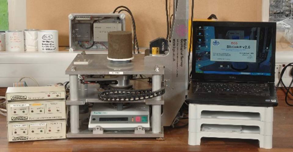
The shrinkage limit test is very rarely carried out in the UK — partly because the British Standard test methods use mercury — but the shrinkage limit is an important parameter when investigating the volume change of clay and mudstone.
‘SHRiNKIT’, the shrinkage limit apparatus developed at BGS, does not use mercury. Specimen dimensions are measured with a laser rangefinder for the calculation of volume change. Weight is measured simultaneously from which water content is calculated. Shrinkage limit is calculated from the plot of water content versus volume.
More information on SHRiNKIT and shrinkage limit test of UK and international soils can be found in the case study (including data on the shrinkage limit of UK and international soils).
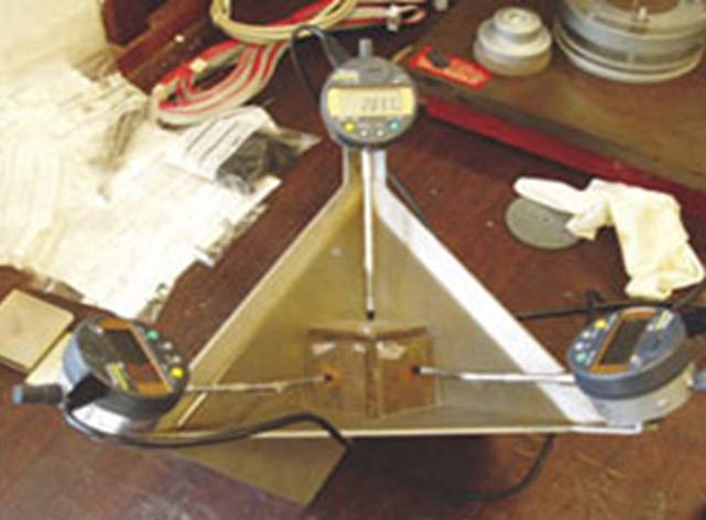
The 3D swell strain apparatus was developed at BGS by adapting a design taken from the International Society for Rock Mechanics (ISRM). The apparatus measures the orthogonal strains of a cube specimen of clay or mudstone immersed in water and subjected to swelling. From the data, the overall volumetric strain is calculated and, if required, the strain anisotropy.
BGS’s design is simple in concept and, whilst fulfilling the criteria of ISRM specification, does not require leak-proof seals for the strain gauges armatures illustrated in the ISRM method.
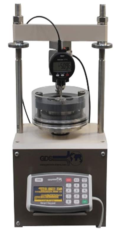
Clay-rich formations are capable of exerting considerable stresses on foundations and services when exposed to an increase in water content from the desiccated state. The 1D swelling pressure test enables the swelling susceptibility of these formations to be determined.
Using the GDS Instruments GDSAOS automated 1D consolidation/swelling pressure apparatus, the swelling of the flooded specimen soil is sensed by a transducer. An electronic feedback system initiates a vertical force sufficient to counteract the swelling strain, which is applied via a stepper motor. The load is logged and the results are summarised in a plot of swelling pressure versus time. The test fulfils the specifications of the British Standards swelling pressure test.
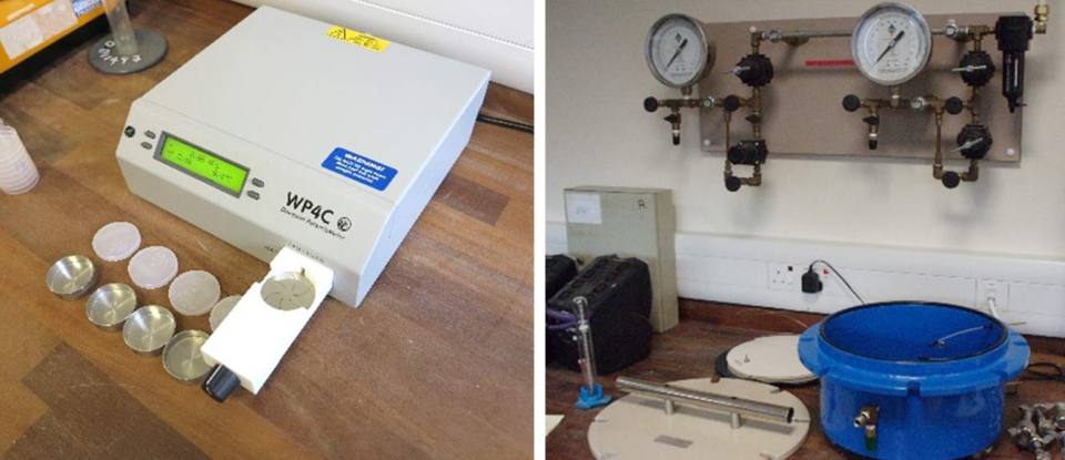
More comprehensive soil moisture characteristic curves can be generated by combining data from both low suction test apparatus, like the gas-plate extractor, and high suction apparatus, like the WP4C dewpoint potentiometer.
These apparatus measure the response of a remoulded soil pat to applied suctions and allow the soil moisture characteristic curve for the soil to be established. The two methods are complementary and together cover a very wide suction range.
Contact
Please contact Matthew Kirkham for further information.
Geophysical laboratories
We have developed specialist apparatus and methods to study the inversion of interrelated parameters of porosity, saturation, density, suction and stiffness from shear wave velocity and electrical resistivity ground surveys. Innovative geotechnical and geophysical property testing has driven the emergence of geotechnical property imaging via geophysical proxy.
This an area that we have led for over a decade (case studies). Laboratory calibration of our field geophysical images has led to new advances in monitoring natural landslides and the condition and deterioration of railway embankments.
Core resistivity imaging system
This system is used for surface scanning of reservoir rocks and electrical imaging of fine sedimentological structures at centimetric scale (Figure 1). Fine-scale sedimentary features and open fractures in saturated rocks are interpreted from the measurements with reference to established relationships between electrical resistivity and porosity.
Our results successfully characterise grainfall lamination and sandflow cross-stratification in a brine-saturated, dune-bedded core sample representative of a southern North Sea reservoir sandstone (shown in Figure 1), studied using the system in constant current, variable voltage mode. In contrast, in a low-porosity marble, identification of open fracture porosity against a background very low matrix porosity is achieved using the constant voltage, variable current mode.
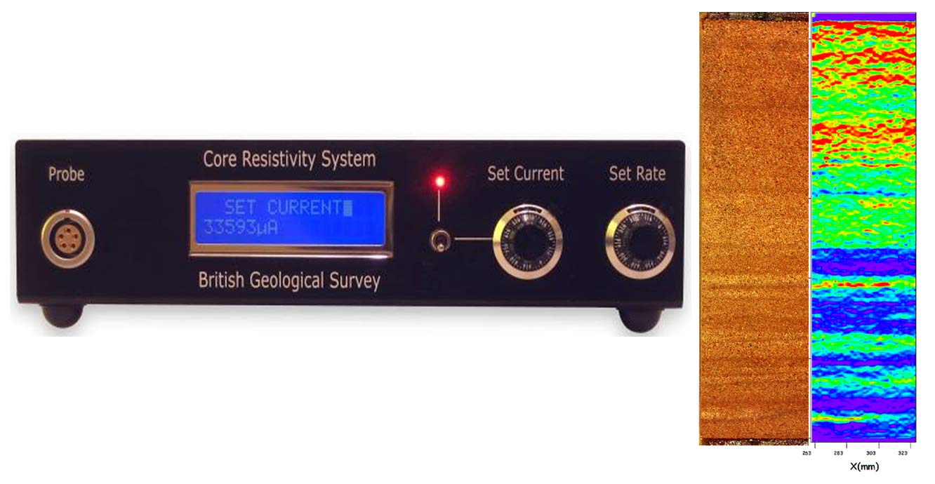

Figure 1 Core resistivity system and image of fining-up sequences in sandstone similar to North Sea reservoir rocks.
See A new apparatus for determining the shrinkage limit of clay soils for more information or view more case studies.
Geophysical/geotechnical proxy
This apparatus is for conditioning samples and testing moisture content, matric suction, density and resistivity (Figure 2). Cells and methods have been devised to control sample wetting and drying phases for the development of geotechnical/geophysical property relationships (Figure 2). We have applied these relationships to field monitoring data to visualise the effect of cyclic water movement on the stability of natural and engineered slopes (Figure 3).
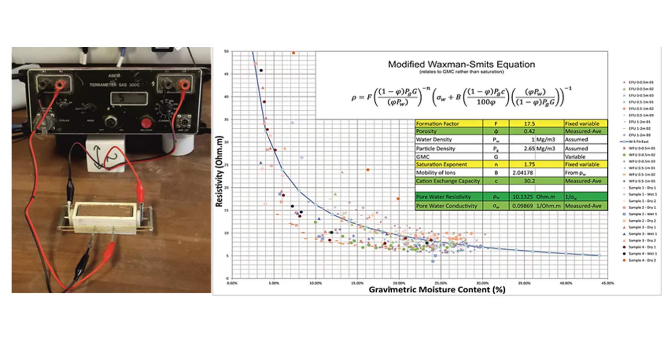
Figure 2 Left: resistivity moisture test cells. Right: resisitivity moisture content property relationship.
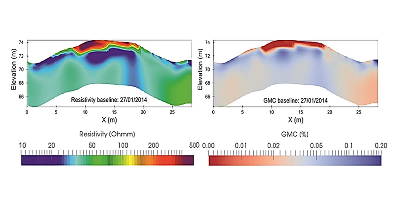
Figure 3 Moisture content distribution throughout a railway embankment via resisitivity proxy.
For further information, see 4D electrical resistivity tomography monitoring of soil moisture dynamics in an operational railway embankment.
Relative topics
Need more information?
You may also be interested in

Science facilities
BGS operates and maintains a wide range of state-of-the-art laboratories and other facilities, which underpin virtually all of our research.
Engineering and Geotechnical Capability
Leading the development and application of field and laboratory infrastructure and long-term management of geophysical and geotechnical property data.