BGS was alerted to the presence of a landslide at Hollin Hill by the landowner during the geological mapping survey in 2004. Subsequently, a visit was made to the farm by the Landslide Response Team during October 2005. As a result of this survey, we have developed a new system of monitoring landslide movement by combining geomorphological mapping, terrestrial LiDAR and real-time monitoring with geophysics.

Hollin Hill, Yorkshire, location map. BGS © UKRI.
Scientific research at this site has been designed to enable BGS to accurately monitor and eventually predict movement of the landslide. It brings together a combination of field surveying and geomorphological, geophysical, engineering and hydrogeological expertise at BGS.
The BGS gratefully acknowledges and thanks the landowner for his help and co-operation with this groundbreaking study.
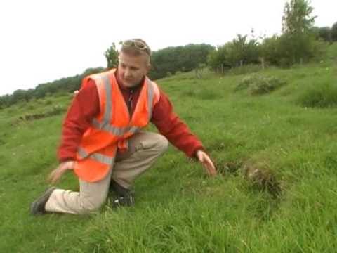

Hollin Hill Landslide Observatory. BGS © UKRI.
The landslide
The Hollin Hill landslide lies to the north of York. It is several hundred metres wide and extends 200 m downslope. Located on the south-facing side of a degraded Devensian ice-margin drainage channel, the slope has an angle of approximately 12°. This landslide has been entered into the National Landslide Database under ID number 15659/1.
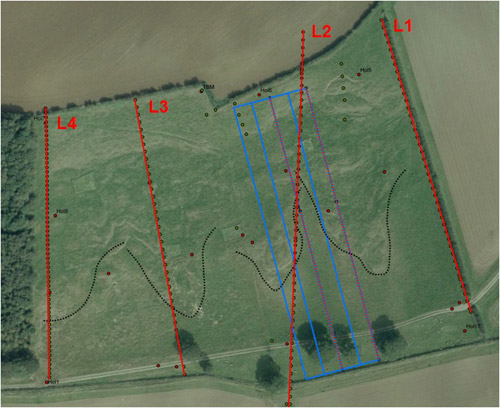
Aerial photograph of the Hollin Hill landslide with the geophysical survey plan. © UKP/Getmapping Licence No. UKP2009/01.
Geology
The slope at Hollin Hill consists of Redcar Mudstone (formerly known as the Lower Lias) at the base, with an outcrop of the Staithes Sandstone Formation (‘Middle Lias’) running across the middle section of the slope. The Whitby Mudstone Formation (‘Upper Lias’) overlies this, with the upper part of the slope composed of the Dogger Formation. Both the Redcar Mudstone and the Whitby Mudstone formations are highly susceptible to landsliding. Movement across the entire slope is due to these two formations.
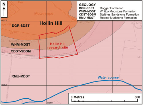
Geology of the Hollin Hill landslide. (Geological map, BGS ©UKRI 2009. Ordnance Survey © Crown Copyright. All rights reserved. Licence number 100017897/2009.)
Detailed geology
The Redcar Mudstone Formation forms the base of the Lias Group and comprises (at maximum) up to 200 m of mainly dark grey mudstones and siltstones; subsidiary thin limestones (concentrated in the lower third), and very fine-grained sandstones. Ironstone beds and nodules are also present (Powell, 1984).
The Staithes Sandstone Formation comprises approximately 20 m (at maximum) of fossiliferous, micaceous, calcareous, very fine- to fine-grained sandstone. It is yellow-brown at outcrop but grey when fresh with interbedded grey siltstone and silty mudstone.
The Whitby Mudstone Formation, which forms the upper part of the Lias Group, typically consists of bluish grey to dark grey, sparsely fossiliferous, fissile, locally bituminous mudstones and siltstones. Bands of calcareous concretions are common at some horizons. At its thickest it reaches about 25–3 0m thickness in the study area.
The Dogger Formation is composed of a massive, fine to medium-grained sandstone, up to 2.7 m in thickness. The matrix is calcareous and the basal part is almost a sandy limestone. Ooliths are present except near the top of the formation (Gaunt et al., 1980).
The landslide
The landslide is largely caused by the movement of the Whitby Mudstone Formation, which is highly prone to landsliding. The landslide is characterised by shallow rotational failures at the top of the slope in the Whitby Mudstone, which move through an area of translational landslide movement and ‘cascade’ over the in situ Staithes Sandstone Formation and feed into four larger-scale, slow-moving (i.e. tens of centimetres per year) lobes of slumped material at the bottom of the slope. Relatively little is known about the hydrogeology of the site. However, a spring line extends across the base of the slope where the Staithes Sandstone overlies the Redcar Mudstone Formation.
The morphology of the slope is complex with numerous isolated shallow failures and slumping. Locally the slope becomes very steep where slipped material has accumulated to form lobes.
Monitoring the landslide
Following on from the initial field mapping of the area, a combination of several techniques and scientific disciplines are being used by BGS to monitor the landslide.
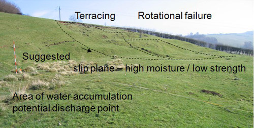
Annotated photograph of the Hollin Hill landslide. BGS © UKRI.
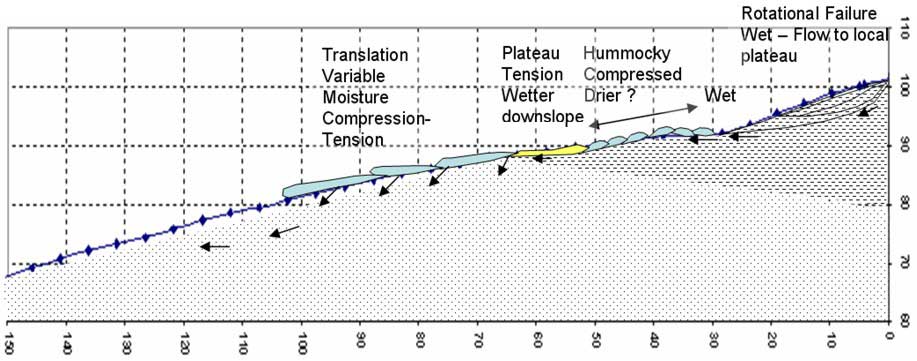
Conceptual model of the Hollin Hill landslide. BGS © UKRI.
LiDAR
Both aerial and terrestrial LiDAR surveys have been carried out at this site. These have provided geologists at BGS with the unique opportunity to study the different technologies for monitoring an active landslide site in the UK.
The initial method of survey is long-range laser scanning (terrestrial LiDAR). The first (baseline) survey recorded the ground surface of the landslide and surrounding area in three dimensions, whilst subsequent surveys record the movement of the slope. Surveys are carried out at six-monthly intervals and the data, collected in the field by LiDAR and GPS, is entered into a computer modelling package. The results are processed to provide data to model the way in which the landslide is moving. Information obtained by the terrestrial LiDAR survey will allow us to monitor the changing shape of the surface.
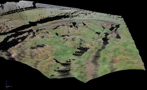
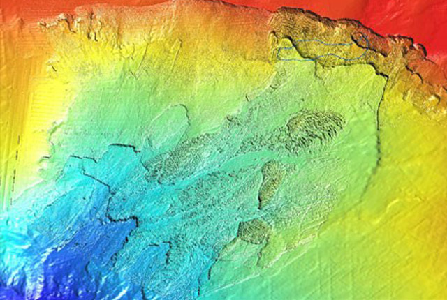
Terrestrial LiDAR scan of the top of the landslide. The backscarp can be seen here.
Geophysics
Geophysics was used at this site to enable us to study the movement of the landslide in three dimensions and to provide geophysical data across the whole of the Hollin Hill research site. The following geophysical techniques were used:
- Geocarta mobile resistivity mapping
- electrical resistivity tomography (ERT) lines (2D) and grids (3D)
- self potential (SP) profiles (2D) and grids (3D)
Electrical resistivity tomography (ERT)
ERT was chosen to provide information on the bedrock geology, the dimensions and the structure of the landslide as cross-sections (2D lines). The 2D ERT lines were surveyed using electrodes at 3 m intervals.
Self potential (SP)
The SP profiles were generated using 5 m electrode spacings; a base electrode (negative) was installed a short distance from the midpoint of each line. A roving electrode (positive) was moved up and down each line in a closed loop so that repeat measurements were made for each electrode location.
ERT and SP in three dimensions
The ERT and SP grids were designed to provide detailed 3D and 2D spatial information relating to the area on and between the two eastern lobes, which has been identified as a preferred location for the monitoring system. This is the grid in purple and blue on the aerial photograph of the Hollin Hill landslide with the geophysical survey plan.
The ALERT system
In the spring of 2008, an Automated time-Lapse Electrical Resistivity Tomography (ALERT) system was permanently installed on the site (Kuras et al., 2009; Ogilvy et al., 2009). The ALERT instrument uses wireless telemetry (in this case, GPRS) to communicate with a computer in the office, which runs control software and a database management system. The control software schedules data capture, whilst the database management system stores and processes the remotely streamed ERT data. Once installed, the system operates automatically with no manual intervention.
Modifications to the ALERT system at this site have included the addition of environmental and geotechnical sensors to monitor rainfall, air pressure, ground movement and pore pressure changes within the landslide. The system is housed in a weatherproof enclosure and is powered by batteries charged by a wind turbine and solar panels.
ALERT system installation
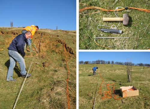
Installing the ALERT system. BGS © UKRI.
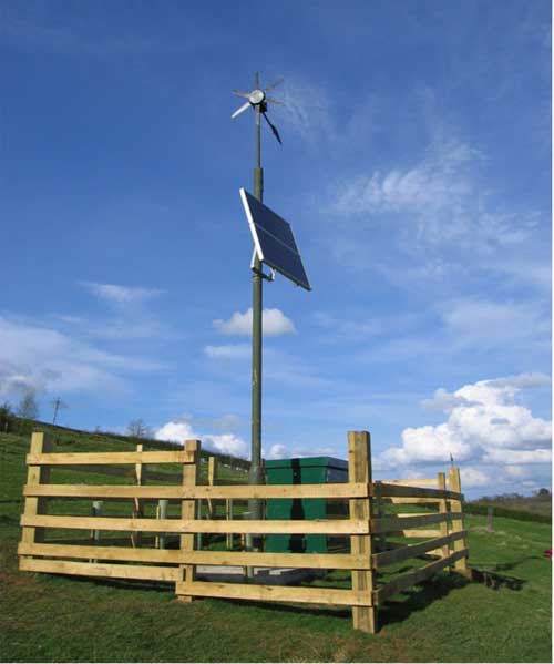
The ALERT system installed. BGS © UKRI.
Preliminary results
Good resistivity contrast between the slipped material and sandstone bedrock has allowed us to use resistivity mapping data and ERT models to define the geometry of the landslide. The resistivity map revealed the extent of the in situ and slipped Whitby Mudstone Formation (low resistivity) and in situ Staithes Sandstone Formation (high resistivity). This data was complemented by the ERT models in which the lobes of slipped mudstone could be distinguished from the underlying sandstone bedrock. In particular, slip surfaces can be seen in the resistivity models where the mudstone lobe has overridden the sandstone bedrock.
A static 3D ERT model was generated from data collected shortly after the ALERT system was installed. The model shows the three-dimensional structure of the landslide and is the reference model for future models to be measured against.
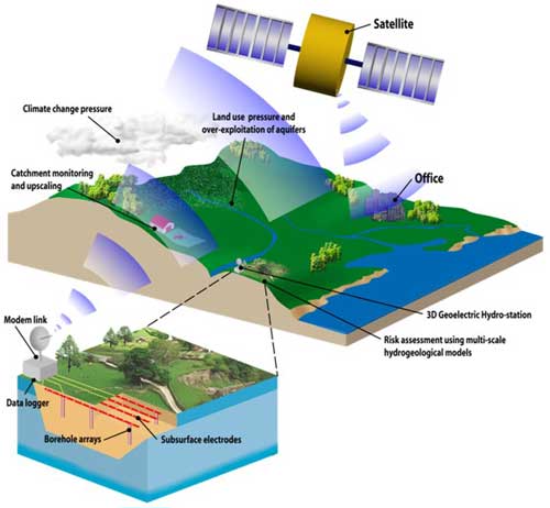
New sensor technology developed by BGS for the real-time electrical imaging of sensitive sites ‘on-demand’. BGS © UKRI.
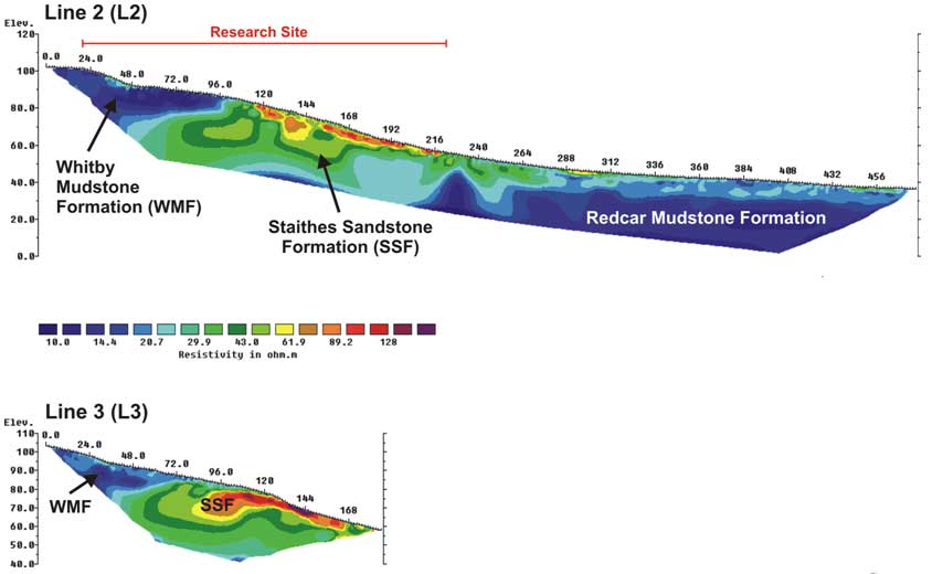
2D ERT model and SP profile. BGS © UKRI.
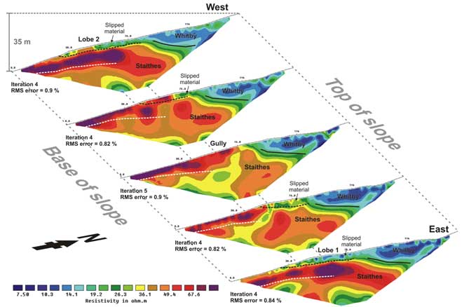
2D ERT models generated from the five lines comprising the ERT survey grid over the two eastern lobes. (Interpretation: dashed black line – slip surface; dashed white line – water table; solid black line – stratigraphic boundary). BGS © UKRI.
Baseline ERT model
The geology of the hillslope is clearly seen on the baseline ERT model. The Whitby Mudstone Formation (WMF) is a clay-rich, low-resistivity formation (green-blue); the Staithes Sandstone Formation (SSF) has lower clay content and is more resistive (pink-white); the underlying Redcar Mudstone Formation (RMF) displays a similar resistivity range to that of the WMF (green-blue). The slipped WMF material of lobes 1 and 2 has overridden the Staithes Sandstone bedrock.
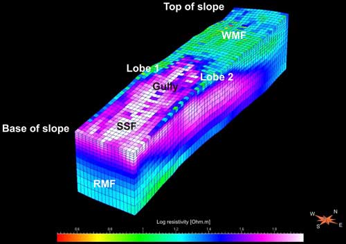
Baseline 3D ERT model of the landslide generated from ALERT data. BGS © UKRI.
References and further reading
Chambers, J E, Weller, A L, Gunn, D A, Kuras, O, Wilkinson, P B, Meldrum, P I, Ogilvy, R D, Jenkins, G O, Gibson, A D, Ford, J R, and Price, S J. 2008. Geophysical anatomy of the Hollin Hill landslide, North Yorkshire, UK. EAGE Near Surface 2008, Krakow, Poland, 15–17 September 2008.
Chambers, J E, Meldrum, P I, Gunn, D A, Wilkinson, P B, Kuras, O, Weller, A L, and Ogilvy, R D, 2009. Hydrogeophysical monitoring of landslide processes using automated time-lapse electrical resistivity tomography (ALERT). EAGE Near Surface Geophysics, Dublin, Ireland, 7–9 September, 2009.
Friedel, S, Thielen, A, and Springman, S M. 2006. Investigation of a slope endangered by rainfall-induced landslides using 3D resistivity tomography and geotechnical testing. Journal of Applied Geophysics, Vol. 60, 100–114.
Gaunt, G D, Ivemy-Cook, H C, Penn, I E, and Cox, B M. 1980. Mesozoic rocks proved by IGS boreholes in the Humber and Acklam areas. Report of the Institute of Geological Sciences, No 79/13. (Institute of Geological Sciences, London: HMSO.)
Jenkins, G O, Jones, L D, and Gibson, A D. 2006. Analysis of the Hollin Hill Landslide, Low Mowthorpe, North Yorkshire: field reconnaissance survey and proposed survey recommendations. British Geological Survey Internal Report IR/06/110. (Nottingham, UK: British Geological Survey.)
Jongmans, D, and Garambois, S. 2007. Geophysical investigation of landslides: a review. Bulletin de la Société Géologique de France, Vol. 178, 101–112.
Kuras, O, Pritchard, J, Meldrum, P I, Chambers, J E, Wilkinson, P B, Ogilvy, R D, and Wealthall, G P, W. 2009. Monitoring hydraulic processes with Automated time-Lapse Electrical Resistivity Tomography (ALERT). Geoscience Reports, Vol. 341(10–11), 868–885.
Ogilvy, R D, Kuras, O, Meldrum, P I, Wilkinson, P B, Chambers, J E, Sen, M, Pulido-Bosch, A, Gisbert, J, Jorreto, S, Frances, I, and Tsourlos, P. 2009. Automated monitoring of coastal aquifers with electrical resistivity tomography. Near Surface Geophysics, Vol. 7(5–6), 367–376.
Pennington, C V L, Foster, C, Chambers, J E, and Jenkins, G O. 2009. Landslide research at the British Geological Survey: capture, storage and interpretation on a national and site-specific scale. Acta Geologica Sinica English Edition, Vol. 83(5), 991–999.
Perrone, A, Iannuzzi, A, Lapenna, V, Lorenzo, P, Piscitelli, S, Rizzo, E, and Sdao, F. 2004. High-resolution electrical imaging of the Varco d’Izzo earthflow (southern Italy). Journal of Applied Geophysics, Vol. 56, 17–29.
Powell, J H. 1984. Lithostratigraphic nomenclature of the Lias Group in the Yorkshire basin. Proceedings of the Yorkshire Geological Society, Vol. 45(1–2), 51–57.
Revil, A, Naudet, V, Nouzaret, J, and Pessel, M. 2003. Principles of electrography applied to self-potential electrokinetic sources and hydrogeological applications. Water Resources Research, Vol. 39(5), SBH 3-1.
You may also be interested in
Landslide case studies
The landslides team at the BGS has studied numerous landslides. This work informs our geological maps, memoirs and sheet explanations and provides data for our National Landslide Database, which underpins much of our research.
Understanding landslides
What is a landslide? Why do landslides happen? How to classify a landslide. Landslides in the UK and around the world.
How to classify a landslide
Landslides are classified by their type of movement. The four main types of movement are falls, topples, slides and flows.
Landslides in the UK and around the world
Landslides in the UK, around the world and under the sea.