Since the mid-1990s, BGS has been researching how carbon dioxide (CO2) can be stored in rocks under the ground. Carbon capture and storage (CCS) is one way Britain and the world can maintain industrial production and economic growth while reducing emissions.


Carbon capture and storage research at BGS
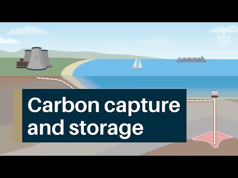
What is carbon capture and storage?
Different options to try to reduce overall CO2 emissions are being investigated, but the main way to reduce CO2 emissions from large industrial sources is called carbon capture and storage, or CCS. CCS involves capturing carbon dioxide (CO2) at emission sources, transporting and then storing or burying it in a suitable deep, underground location. CCS can also mean the removal of CO2 directly or indirectly from the atmosphere.
What is carbon capture and storage? Responding to the impact of climate change. BGS © UKRI.
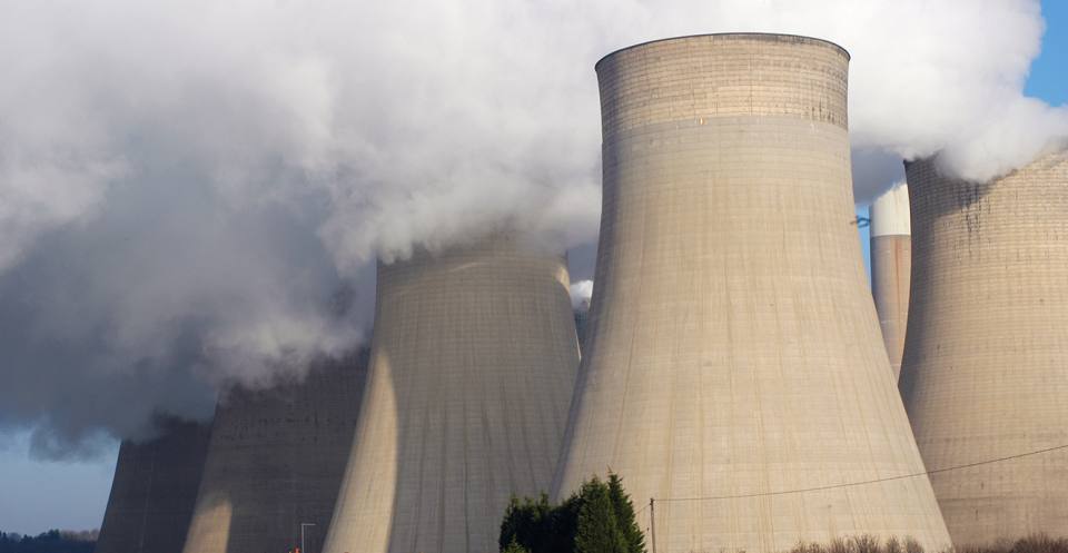
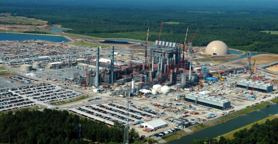
Fossil fuel-related CO2 emissions reached 32 Gigatonnes in 2010. These emissions come from industrial processes and stationary emission sources, such as power stations, cement production and refineries. About 50 per cent of the total anthropogenic (human-made) CO2 emissions between 1750 and 2010 have been produced in the last 40 years.
CO2 can be captured from large sources, such as power plants, natural gas processing facilities and some industrial processes. Capture from the open atmosphere is also possible.
Where fossil fuels are burnt at power plants, there are three techniques to remove or ‘scrub’ CO2:
- post-combustion
- pre-combustion
- oxyfuel combustion
Post-combustion
In this process, CO2 is removed after burning the fossil fuel. CO2 is captured (‘scrubbed’) from the exhaust (or ‘flue’) gases. This is the method that would be applied to most conventional power plants as it can be retro-fitted. The technology is well understood and is currently used in other industrial applications.
Pre-combustion
This technique traps CO2 before burning the fossil fuel. First, the fossil fuel is partially burned in a ‘gasifier’ to form synthetic gas. CO2 can be captured from this relatively pure exhaust stream. The process also produces hydrogen, which can be separated and used as fuel.
Pre-combustion is used in the production of fertiliser, chemical gas fuel and power production. It is a cheaper option than post-combustion but cannot be retro-fitted to older power plants.
Oxyfuel combustion
In oxyfuel combustion, the fossil fuel is burned in oxygen instead of air. The resulting flue gas consists of mainly CO2 and water vapour. The water condenses through cooling and the result is almost pure CO2 that can be transported and stored.
Electricity plant processes based on oxyfuel combustion are sometimes referred to as ‘zero emission’ as nearly all the CO2 is captured. It is possible that some CO2 will dissolve in the condensed water, so the water may have to be further treated. Whilst it may be the most effective method of the three, the initial oxygen burning process is energy intensive.
Hydrogen production
Another way of reducing atmospheric emissions of CO2 in some areas, such as heavy goods vehicles, where battery-based electric power is unsuitable, and trains, and domestic heating and gas cookers, is to convert to hydrogen.
Whilst hydrogen produced by a process called electrolysis of water using renewable power has very low CO2 emissions, it is currently expensive. A cheaper and more mature option to enable the conversion to hydrogen to be started is to produce hydrogen from natural gas. This process is called methane reformation. However, the CO2 produced in the reforming process must also be captured and stored.
Direct air capture
It is possible to capture CO2 directly from the open atmosphere, but this is still being researched.
The estimated energy needed for air capture is only slightly more than for capture from large emission sources. The costs may be higher as well, but may be feasible for dealing with emissions from diffuse sources.
After capture, CO2 must be transported to suitable storage sites. Pumping it though pipelines is the cheapest form of transport and is a well known and reliable technology.
There are 5800 km of CO2 pipelines in the United States transporting CO2 to oil production fields, where the CO2 is injected to help produce more oil. This process is called enhanced oil recovery or EOR.
However, the increased number and carrying capacity of pipelines needed for a large-scale CCS industry will require further studies of pipeline safety, particularly in heavily populated areas or areas of high earthquake activity.
Ships and road tankers can also be used to transport CO2 for small scale applications.
CO2 can be stored in two main ways:
Deep ocean storage will increase ocean acidification, a problem that also stems from the excess of CO2 already in the atmosphere and oceans.
Geological formations are currently considered the most promising storage sites. Areas such as the North Sea and the US Gulf Coast are believed to contain a large amount of geological storage space.
The Intergovernmental Panel on Climate Change (IPCC) says that for well-selected, well-designed and well-managed geological storage sites, CO2 could be trapped for millions of years, retaining over 99 per cent of the injected CO2 over 1000 years.
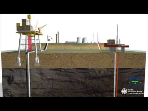
Deep geological formations
Storage in deep geological formations is also known as ‘geo-sequestration’. In this technique, CO2 is converted into a high pressure, liquid-like form known as ‘supercritical CO2’. Supercritical CO2 behaves like a runny liquid, a bit like WD40, and is injected directly into sedimentary rocks. The rocks may be in old oil fields, gas fields, or in saline formations — rocks with porous spaces filled with salty water. Unmineable coal seams and some volcanic rocks are also suggested storage sites.
Various physical structures prevent CO2 from escaping to the surface. These include impermeable ‘caprocks’ and geochemical trapping mechanisms.
Enhanced oil recovery (EOR)
This process is already understood and has been carried out for many years. In the United States, approximately 30–50 million tonnes of CO2 are injected annually into declining oil fields, to increase oil production. This option is attractive for CO2 storage because costs of injection may be partly offset by the sale of additional oil that is recovered. However, the subsequent burning of the additional oil recovered through EOR will offset much or all of the reduction in CO2 emissions.
‘Unmineable’ coal
‘Unmineable’ coal, which is coal that is too deep or difficult to mine, can be used to store CO2. The coal absorbs the CO2, provided the coal is permeable enough to allow CO2 to penetrate. During this process, the coal releases previously absorbed methane (CH4), which can then be recovered and used. This is called enhanced coal-bed methane or ECBM.
The sale of the CH4 can offset some of the cost of the CO2 storage. However, as in EOR, burning the resultant CH4 would produce CO2 which would reduce some of the benefit of storing the original CO2.
Saline aquifers
Some deep rock formations contain highly concentrated brine (salty water). This is present in the rock pores and acts like a huge sponge. These are known as ‘saline aquifers’. Their main advantage for CCS is their large storage potential and their abundance. For example, large saline aquifers underlie much of the North Sea, mainland Europe and the Gulf Coast of Texas in the USA.
The main disadvantage of saline aquifers is that relatively little is known about them compared to oil fields. However, current research shows that several trapping mechanisms immobilise the CO2 underground, reducing the risk of leakage. Unlike storage in oil fields or coal beds, there is no useful byproduct to offset the cost of storage.
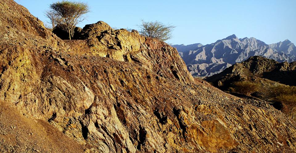
Mineral storage
In mineral storage, captured CO2 is reacted with naturally occurring iron (Fe), magnesium (Mg) and calcium (Ca) minerals. This is called ‘mineral carbonation’ and occurs naturally in the weathering of rock over time. Such minerals are very abundant and very stable. As a result, the re-release of CO2 into the atmosphere does not happen.
However, these carbonation reactions are very slow under normal conditions and to speed it up would need energy to increase temperature and pressure to ideal levels.
The IPCC estimates that a power plant equipped with CCS using mineral storage will need 60–180 per cent more energy than a power plant without CCS.
What are the costs and risks of CCS?
CO2 storage regulations require that storage operations be rigorously monitored for a number of reasons, including:
- verifying the amount and composition of CO2 being put into underground storage
- understanding how the CO2 is behaving once underground
- providing early warning if things are not going as planned
- providing assurance of long-term storage integrity
- measuring any leakage that might occur
Regulatory frameworks governing geological CO2 storage are being developed worldwide. In Europe, an EC Directive says that the issues of leakage and potential long-term stewardship of storage sites must be addressed if the potential for CO2 capture and storage to provide substantial reductions in atmospheric CO2 emissions is to be realised.
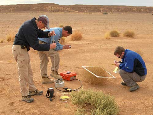
Monitoring of a CO2 storage site starts before the CO2 storage begins. This builds up a baseline picture of the geology and the environmental conditions before any CO2 is stored.
A strategy for baseline surveying will be built into the overall assessment of storage site suitability, referred to as the ‘site characterisation’. Once CO2 injection has started, monitoring surveys will be repeated at specified intervals to build up ‘time-lapse’ images of site properties.
Results and measurements from the time-lapse monitoring surveys can then be compared to the baseline survey to see if and how different parts of the storage system are changing. The storage site will need to be monitored throughout the injection phase and for some time after injection has ceased, to ensure that the system is behaving as predicted and is likely to continue to be safe in the future.
A range of tools and technologies can monitor onshore and offshore CO2 storage sites. Monitoring systems can be categorised as deep focused or shallow focused.
Deep-focused monitoring can be run from the surface (e.g. surface seismic or gravimetry) or from well-bores (e.g. well logging, pressure/temperature measurement). It aims to identify and characterise changes in the storage reservoir as injection proceeds, including the movement of CO2 within the reservoir and its immediate surroundings. Deep monitoring systems also give early warning should CO2 move to shallower depths.
Shallow monitoring systems detect and measure CO2 that has migrated into shallow geological formations, to the soil or seabed, or leaked to the atmosphere or into sea water. Shallow-focused methods can be airborne (e.g. satellite interferometry), deployed at the surface (e.g. atmospheric measurements and surface flux), or can be run from shallow well-bores (e.g. geochemical sampling).
BGS undertakes research into many different monitoring tools and their use in monitoring systems. We have designed an online monitoring system selection tool for IEAGHG to assist storage operators select appropriate technologies for their sites.
It is fundamental that a storage site must be operated safely and that, if CO2 does unintentionally leak, it can be detected and measured. Leaking CO2 could be a hazard, in some circumstances, because CO2 at high concentrations can cause suffocation: it is an asphyxiant. It would also mean that the process would not be working as a climate change mitigation method. However, for well-selected, well-designed and well-managed geological storage sites, the IPCC says that risks are low. CO2 could be trapped for millions of years and well-selected stores are likely to retain over 99 per cent of the injected CO2 over 1000 years.

Regulation
The directive on the geological storage of CO2 ( ‘CCS Directive’) establishes a legal framework for the environmentally safe geological storage of CO2. It covers all CO2 storage in geological formations in the EU and the entire lifetime of storage sites. It also contains provisions on capture and transport.
Will earthquakes cause CO2 to leak?
CO2 storage sites are normally positioned away from seismic (earthquake) activity and active faults. However in some tectonically active parts of the world like Japan, New Zealand or Greece, CO2 may have to be stored closer to potential earthquake zones.
In October 2004, the Nagaoka CO2 storage and monitoring project in Japan experienced a large earthquake during a CO2 injection trial. The injection stopped immediately and the site was monitored for possible CO2 leakage, however, no leakage was detected. In December 2004, injection was started again and a total of 10 400 tonnes of CO2 has been safely stored. If a site is well understood, even a large earthquake in close proximity to a CO2 storage site should not result in leakage.
Human activities can also cause seismic activity. The most common form of ‘induced seismicity’ is caused by mining, oil and natural gas operations, groundwater and large dammed reservoirs. In the extraction of groundwater or oil and natural gas, changes in pressure cause instability in the affected geology.
De-pressurisation causes the geology to shrink or collapse slightly, like a deflating ball. This process is well known and well-understood. It can be managed in oil and gas fields, thus should not be a problem in CCS.
Capturing and compressing CO2 requires a lot of energy and increases the fuel needs of a coal-fired electricity plant by 25–40 per cent. These and other costs are estimated to increase the cost of electricity from a new power plant with CCS by 21–91 per cent. These estimates apply to purpose-built plants near a storage location. However, applying the technology to pre-existing plants or plants far from a storage location will be more expensive. As a result, CCS makes electricity power stations more expensive to build and electricity more expensive to buy. However, the costs of the impacts of climate change will be far higher.
The economic feasibility of CCS on a global scale largely depends on the value and price that governments and people put on environmental and ecosystem viability. If the penalty price for emitting CO2 is high then there is a financial incentive to adopt CCS and it will become economical quickly. If the penalty price remains low, CCS will be slow to develop because there is no incentive. When CCS technology is better developed, its costs may lower. Some people suggest that money spent on CCS will divert investments away from other solutions to climate change.
Reducing CO2 emissions from industrial processes
We will look at five ways in which industrial processes might be made less carbon intensive through the application of CCS. The five options all rely on the storage of CO2 onshore or offshore, in a saline aquifers or depleted gas fields.
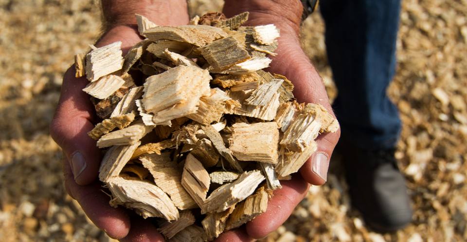
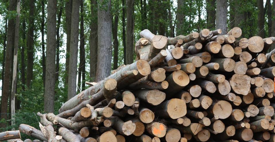
Biomass fuel includes wood, agricultural and food-processing wastes, as well as sewage sludge and animal manure. Using crop waste, sewage or manure — wastes that are continually available — to generate electricity offers environmental benefits by preserving precious landfill space and reducing overall emissions.
Burning wood produces very little sulphur dioxide (SO2) when compared with burning coal. However, some biomass power plants show relatively high nitrogen oxide (NOx) emissions when compared to other combustion technologies. Both SO2 and NOx have serious effects on both the environment and human health.
Biomass can be burnt directly or converted to gas first. Power plants that burn biomass fuel directly do so in boilers that supply steam for the same kind of generators used to burn fossil fuels. In biomass gasification, biomass is converted into methane (CH4) that can then fuel a variety of power plant forms: steam generators, combustion turbines, combined cycle technologies or fuel cells.
The main benefit of biomass gasification, compared to direct combustion, is that extracted gases can be used in a variety of power plant forms.
Cost
Conventional CCS on a fossil fuel power station can reduce CO2 emission by over 95 per cent. However, burning biomass in a boiler coupled with CCS allows a power station to have negative emissions overall. This is because the original biomass vegetation will have absorbed CO2 through its lifetime and the CO2 captured from its burning will be isolated from the atmosphere in storage. Thus even though CCS would increase the cost of electricity from a biomass power plant, customers would know that electricity produced there would actually be reducing the CO2 content of the atmosphere, making this technology particularly attractive.
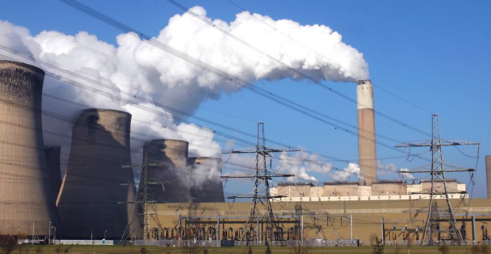
CCS will be a key option for reducing emissions in countries reliant on coal-based electricity generation.
Capture
The concept is to capture CO2 produced by burning coal in power stations, compress it, pipe it away from the plant and then store it deep underground. It will be trapped there beneath impermeable layers of rock that will prevent it from coming back to the ground surface or sea bed.
Cost
The machinery used in CCS will use between 10 and 40 per cent of the energy produced by a power station. This means that electricity will be more expensive to buy. However, a power station equipped with CCS could reduce its CO2 emissions by over 95 per cent and thus the extra cost might be justified.
It may be difficult to choose between electrical power plants with CCS and renewable energy sources on the basis of cost. This is because in some countries (e.g. Britain) renewable electricity generation is encouraged by Government subsidy, whereas CCS development is not.
An integrated gasification combined cycle, or IGCC, power station is one is that turns coal into synthetic gas (syngas) before it is burnt.
Capture
Impurities in the syngas, like CO2, can be removed before it is burnt. The syngas is used to power a gas turbine generator for electricity whose waste heat is passed to a steam turbine system to further increase efficiency.
Cost
It may be difficult to choose between electrical power plants with CCS and renewable energy sources on the basis of cost.
The machinery used in CCS will use between 10 and 40 per cent of the energy produced by a power station. This means that electricity will be more expensive to buy. However, a power station equipped with CCS could reduce its CO2 emissions by more than 95 per cent and thus the extra cost might be considered justifiable.
Refineries produce the transportation fuels that account for a large and growing share of the world’s energy-related CO2 emissions. Refineries are large CO2 emitters because they use so much heat and electrical energy on site and the refining processes itself sometimes produce CO2.
The manufacture of ammonia, alcohol and synthetic liquid fuels also produces CO2. Smelters and cement plants emit CO2, mainly because fossil fuel is burnt to produce heat and steam, but also because some of the chemical processes involved produce CO2.
Capture
The main difference between CO2 capture at a refinery and at a power plant is that the CO2 emissions are more dispersed in a refinery; they would likely have to be captured from several points.
In the manufacture of ammonia, alcohol, and synthetic liquid fuels, if the CO2 captured is not sold or used for another process, it is released straight to the atmosphere (known as ‘venting’). In some of the processes a richer or even relatively pure CO2 stream is emitted to the atmosphere, meaning that capture of the CO2 is more cost-effective.
In the case of smelters and cement plants, the technology options for capturing CO2 are essentially the same as they are for power plants that burn fossil fuels.
Cost
There are few published studies of the costs of refinery, steel, ammonia or cement plant CO2 capture.
One study into post-combustion capture at refineries estimates that only 40–50 per cent of refinery emissions are suitable for capture at costs of €90–120 per tonne of CO2. These costs would increase significantly if more CO2 sources were to be captured.
- More information at CO2 capture for refineries, a practical approach
In the natural gas processing industry, corrosive ‘acid gases’ (typically CO2 and hydrogen sulphide (H2S)) are removed from gas before it can be transported or used.
Capture
What we call ‘natural gasn is actually a mixture of gases. It is typically at least 90 per cent methane (CH4), plus other hydrocarbons such as ethane (C2H6) and propane (C3H8). Natural gas often also contains nitrogen, oxygen, CO2, sulphur compounds and water.
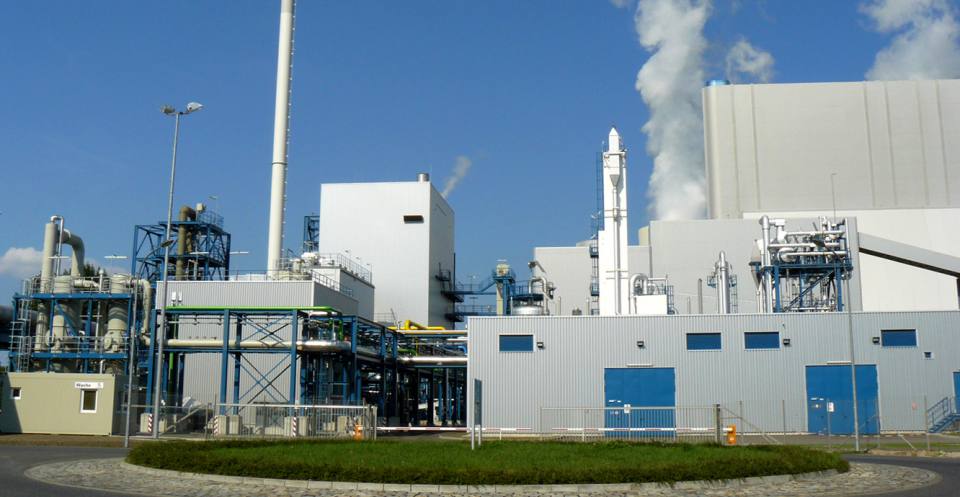
Gas containing high volumes of these impurities cannot be burned efficiently and safely. An example is the natural gas produced at the Sleipner Field in the North Sea, which contains unusually high levels (about 9 per cent) of CO2. Customers want CO2 levels less than 2.5 per cent so a special processing platform called Sleipner-T now separates CO2 from the natural gas.
The Sleipner-T plant produces about 1 million tonnes of pure CO2 per year, which is injected into a deep saline aquifer below the North Sea. Sleipner is a key demonstration site for CCS technology in Europe.
Cost
In most cases it is cheaper to vent the gas into the atmosphere; burying CO2 increases the overall cost of natural gas to the consumer. However, in some countries a ‘carbon tax’ is charged to companies that emit CO2. In Norway, the government charges the company producing the natural gas being released into the atmosphere. To avoid paying this tax at the Sleipner Field, all of the CO2 extracted since 1996 has been stored underground.
Types of thermal power plant
A power station can generate electricity by burning fossil fuel, but they can also be designed to burn fossil fuels and biomass together (called co-firing) or just biomass. Most co-firing power plants burn solid biomass like wood and agricultural waste along with coal, but some can burn a mix of natural gas and biogas. Because burning biomass is carbon neutral, co-firing reduces the emission of greenhouse gases.
The main advantage of co-firing is that it can be done in existing power plants with little or no modification, allowing for inexpensive and rapid reductions in greenhouse gases.
In a combined cycle power plant (CCPP) or a combined cycle gas turbine (CCGT) plant, a gas turbine generates electricity and the waste heat is used to make steam to generate additional electricity via a steam turbine; this last step enhances the efficiency of electricity generation. A combined cycle power plant is more efficient than a conventional power plant because it uses a higher proportion of the energy that the fuel produces when it burns. Most new gas power plants in North America and Europe are of these types.
The integrated gasification combined cycle, or IGCC, is a process that turns coal into syngas before it is burnt. The impurities in the syngas, like CO2, can also be removed before it is burnt. The syngas is often used to power a gas turbine generator for electricity whose waste heat is passed to a steam turbine system. If CO2 is removed before burning (pre-combustion), it can be stored in deep geological formations.
In a combined heat and power plant (also known as a co-generation plant), waste heat is used simultaneously to generate more electricity and heat for industrial and domestic heating, including for houses, hospitals and schools. Ordinary power plants that burn coal, petroleum or natural gas do not convert all of their heat into electricity. In most fossil fuel power plants, more than half is lost as waste heat.
A combined heat and power plant can reach efficiency of up to 89 per cent, compared with 55 per cent for the best conventional plants. This means that less fuel is needed to produce the same amount of useful energy.
A fossil-fuel power plant is one that burns fossil fuels such as coal, natural gas or petroleum (oil) to produce electricity. Fossil-fuel power plants are designed on a large scale for continuous operation. In many countries, such plants provide most of the electrical energy, or the ‘baseload’. A fossil-fuel power plant uses a turbine that turns an electrical generator. The turbine may be turned by steam, gas or sometimes an internal combustion engine.
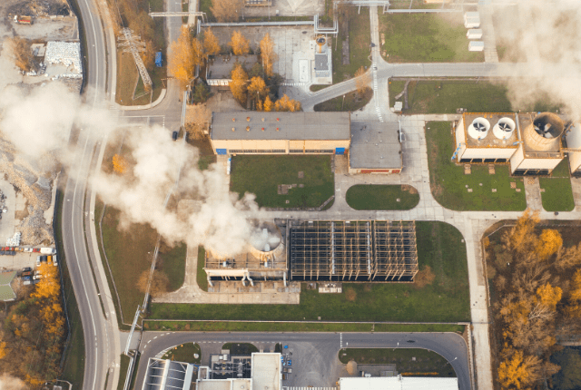
Power plants produce byproducts. Waste heat is released to the atmosphere, often via a cooling tower, a river or lake water as a cooling medium. Waste gas (flue gas) from burning of the fossil fuels is discharged to the air; this contains CO2 and water vapour, as well as other substances such as nitrogen, nitrous oxides, sulphur oxides and (in the case of coal-fired plants) fly ash and mercury. Solid waste ash from coal-fired boilers must also be removed, and some coal ash can be recycled for building materials.
You may also be interested in
Discovering Geology
Discovering Geology introduces a range of geoscience topics to school-age students and learners of all ages.

Discovering Geology: climate change
What is the difference between weather and climate? what causes the Earth’s climate to change and what are the impacts? Find out more with our Discovery Geology climate change resources.
What causes the Earth’s climate to change?
Geological records demonstrate that there have been a number of large variations in Earth’s climate in the past.

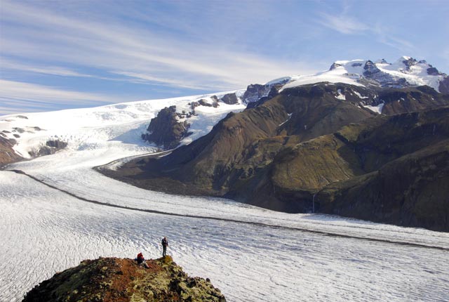
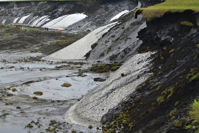
Impacts of climate change
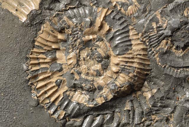
Temperature rises can affect agriculture, sea levels and the frequency of extreme weather incidents. We can study past climate change by looking at the evidence in rocks, fossils and changes in the landscape.
The carbon story
The carbon cycle describes the process in which carbon atoms continually travel from the atmosphere into the Earth, then released back into the atmosphere.

The greenhouse effect
Gases in the Earth’s atmosphere act as an insulating blanket around the planet, trapping more of the Sun’s heat.
What are we doing about climate change?
BGS is committed to research aimed at slowing down the effects of a changing climate, whilst helping society to become resilient to climate change.
Footnotes
1. last 40 years
Source: https://www.ipcc.ch/site/assets/uploads/2018/02/ipcc_wg3_ar5_summary-for-policymakers.pdf